
What is Continuity Test?
Continuity Test is an electrical check that determines whether a complete conductive path exists between two points. A multimeter sends a small test current through the isolated circuit and measures resistance. Low resistance or an audible tone usually indicates continuity, while high resistance or no tone indicates an open path.
Quick Facts About Continuity Test
Category
Electrical diagnostic test
Measured by
Resistance in ohms
Typical tool
Digital multimeter
Used for
Finding open wires and checking connections
Common confusion
Continuity does not confirm correct voltage or polarity
Also called
Continuity Check, Circuit Continuity Test
Key Takeaways About Continuity Test
- Turn off and isolate power before testing continuity on wiring, components, or circuits.
- A low resistance reading usually indicates an unbroken conductive path.
- An open reading can indicate a broken wire, loose connection, blown fuse, or failed component.
- Continuity testing does not prove that a circuit is safe or correctly energized.
Understanding Continuity Test
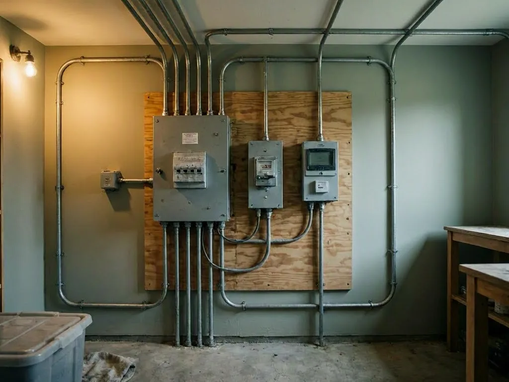
Continuity Test checks for a complete electrical path between two points. The path may pass through a wire, cable, fuse, switch, motor winding, or conductive part. A complete path has low resistance. A break creates an open circuit. It has very high resistance or no measurable connection.
Related glossary terms: Ohm, Polarity Test, Electrical Grounding.
A digital multimeter normally performs this check in resistance or continuity mode. The meter sends a small current through the isolated path. It measures the result. Many meters produce an audible tone below a set resistance level. The level differs by meter. The tone doesn't replace the displayed ohm reading.
How Continuity Test Works, Is Measured, or Is Used?
Before testing, switch off the circuit. Verify that no voltage remains with an appropriate voltage tester. Disconnect at least one conductor or component end. Do this when parallel paths could affect the reading. Place one probe on each test point. Then read the display or listen for the meter tone.
A reading near zero ohms usually indicates a sound conductor. The probes and contact points add some resistance. A reading marked OL, infinity, or very high resistance usually indicates an open path. Test leads can be checked first by touching the probe tips together. This confirms that the meter and leads respond correctly.
- Test a wire end to end to find a break.
- Test across a fuse to check whether the fuse element remains intact.
- Test a switch in each position to confirm that the contacts open and close.
Why Continuity Test Matters?
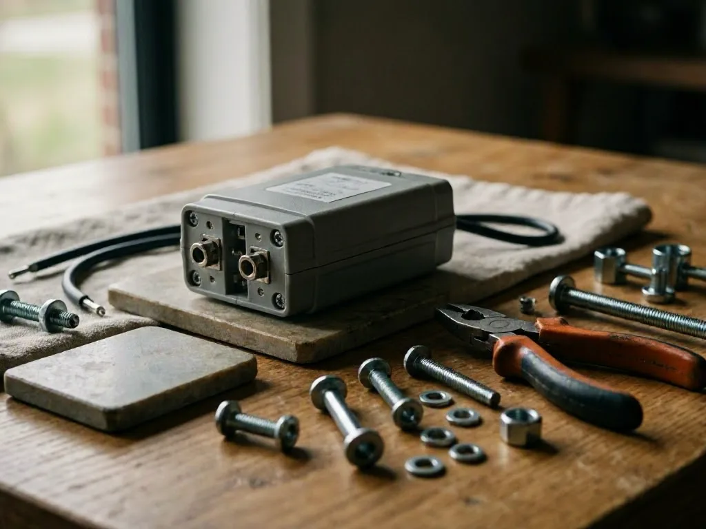
Continuity testing helps locate faults without replacing parts at random. An open conductor reading can explain a dead receptacle, nonworking light, or failed equipment connection. It can also explain an intermittent control. The result narrows the fault area before more voltage or insulation checks.
The test also supports electrical troubleshooting after installation or repair. It can reveal loose terminals, damaged cable, wrong splices, and a blown fuse. Continuity alone doesn't show whether a conductor carries its rated current. It doesn't show damaged insulation or correct circuit polarity.
When Continuity Test Matters Most?
Use this test on deenergized wiring during electrical inspection, repair, and installation work. it's useful after a cable has been pulled through conduit. It's also useful after a terminal has been replaced. Use it when a circuit shows an intermittent fault. Testing each conductor separately can find a broken path. The path may hide inside a wall or cable jacket.
Safety becomes critical near line voltage, generators, capacitors, and connected electronic equipment. Disconnect power sources and stored energy before connecting an ohmmeter. Applied voltage can damage the meter and create a shock hazard. In Cincinnati, a 24-hour electrician may use continuity testing during urgent troubleshooting. The test remains one step in a broader diagnostic process.
How to Evaluate Continuity Test?
- Confirm the circuit is deenergized with a properly rated voltage tester before connecting continuity probes.
- Check that the meter leads show near-zero resistance when touched together.
- Compare the measured resistance with the conductor length and the equipment manufacturer’s specifications.
- Test each wire separately when parallel paths could create a misleading low-resistance reading.
- Treat OL, infinity, unstable readings, or unexpected resistance as signs that further testing is needed.
Related Concepts Compared
Continuity Test vs. Resistance Test
A resistance test measures the opposition to current in ohms. A continuity test is a practical pass-or-fail check for a conductive path, often supported by an audible meter tone.
Continuity Test vs. Voltage Test
A voltage test checks electrical potential between points, usually on an energized or recently isolated circuit. A continuity test checks a path with the circuit deenergized.
Continuity Test vs. Polarity Test
A polarity test confirms that conductors connect to the correct terminals, such as line, neutral, and ground. Continuity only shows that a conductive path exists.
Continuity Test vs. Insulation Resistance Test
An insulation resistance test applies a higher test voltage to evaluate leakage through insulation. A standard continuity test uses a small current and cannot identify all insulation defects.
Expert Note
Remove parallel connections before relying on a continuity result. A low reading can pass through another component or conductor instead of the intended wire. For critical circuits, compare continuity findings with voltage, polarity, and insulation tests.
Common Mistakes or Myths About Continuity Test
- Testing a live circuit with the meter set to continuity or resistance.
- Assuming an audible tone proves the wire can carry its full rated current.
- Leaving connected components in parallel and misreading an alternate conductive path.
- Treating continuity as proof that line, neutral, and ground have correct polarity.
Continuity Test in Practice: A Real-World Example
A hallway light does not turn on, even after the lamp and switch are replaced. With power isolated, a technician tests the cable between the switch box and fixture. The meter shows OL, identifying an open conductor that requires repair or replacement.
Sources & Further Reading on Continuity Test
- Fluke, What Is Continuity?
- OSHA, 29 CFR 1910.333, Selection and Use of Work Practices
Related Services
Related Terms
Ohm
Ohm is the SI unit of electrical resistance, identified by the symbol Ω. One ohm of…
Polarity Test
Polarity Test is a check that confirms electrical connections place the hot, neutral, and grounding conductors…
Electrical Grounding
Electrical Grounding is a safety system that connects electrical equipment and circuits to the earth or…
Short Circuit
Short Circuit is an unintended electrical path with very low resistance that allows excessive current to…
ElectricianCincinnatiOH.com
Have Questions About Continuity Test?
Contact ElectricianCincinnatiOH.com for practical guidance on Continuity Test and related 24 hour electrician work in Cincinnati.