
What Is a Wiring Diagram?
A Wiring Diagram is a visual plan that shows how electrical wires, devices, terminals, and protective components connect within a circuit. Standard symbols represent parts, while lines show electrical paths and connection points. Electricians use the diagram to trace circuit operation, identify conductors, and compare installed wiring with the intended design.
Quick Facts About Wiring Diagram
Category
Electrical documentation
Used for
Circuit tracing and troubleshooting
Common confusion
Confused with a physical wiring layout
Also called
Circuit Diagram, Electrical schematic
Often discussed with
Electrical Troubleshooting, Electrical Wiring Repair
Key Takeaways About Wiring Diagram
- Symbols show components, while lines show their electrical connections.
- A diagram helps trace a circuit from its source to its load.
- A wiring diagram is not the same as a physical layout drawing.
How Wiring Diagram Works
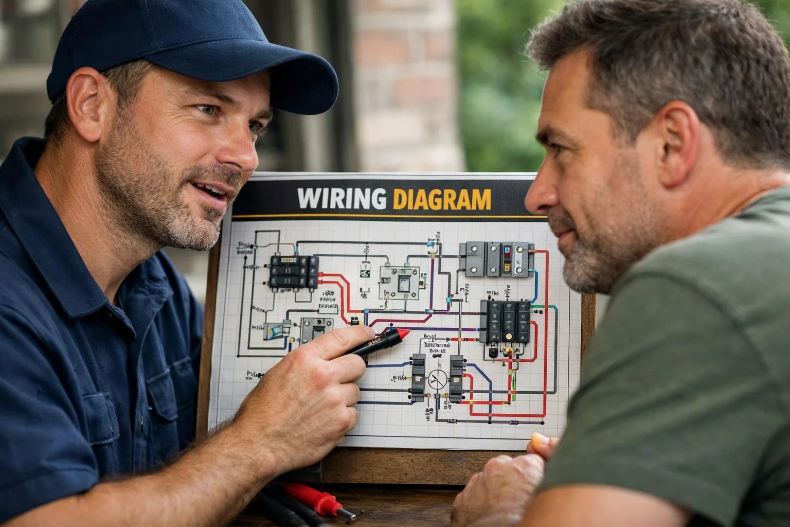
Wiring Diagram works by representing circuit parts with recognized symbols and showing their relationships with labeled lines. The lines may identify hot, neutral, grounding, or control conductors. A technician follows each path from the power source through switches, protective devices, and loads to understand how the circuit should operate.
Related glossary terms: Branch Circuit, Continuity Test, Junction Box.
During troubleshooting, the diagram provides a reference for testing voltage, continuity, and connection points. The technician compares the drawing with the installed wiring, then checks whether each conductor reaches the correct terminal. A branch circuit diagram may show a breaker, cable, receptacles, and lighting equipment in one connected path. A junction box diagram can show how conductors are joined and routed onward.
From the Cincelux Electric team
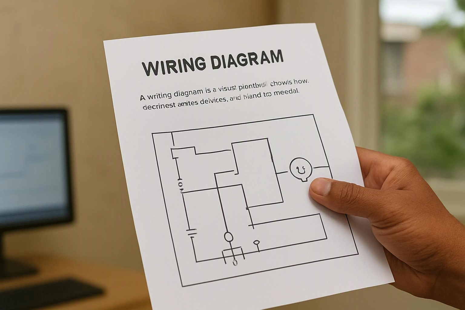
When we troubleshoot a circuit, we use the wiring diagram to identify expected connection points before testing the installation. We compare the diagram with the actual conductors, labels, terminals, and devices so an unexpected connection does not guide the diagnosis.
Wiring Diagram in Practice: A Real-World Example
A homeowner reports that a basement receptacle loses power when a nearby switch operates. A wiring diagram helps trace the shared conductors and locate the connection that links the receptacle and switch.
Related Terms
Branch Circuit
A branch circuit is a wiring path that carries electricity from a panelboard to outlets, lights…
Continuity Test
A Continuity Test is an electrical check that determines whether a complete conductive path exists between…
Junction Box
A Junction Box is an enclosure that houses electrical wire connections, splices, and branch points. The…
Wire Gauge
Wire Gauge is a standardized way to describe a conductor’s diameter and current-carrying capacity. The gauge…
Cincelux Electric
Have Questions About Wiring Diagram?
Contact Cincelux Electric for practical guidance on Wiring Diagram and related 24 hour electrician work in Cincinnati.